Phys 3041 Notes
©1997 Jonathan Maps. These notes may not be redistributed or duplicated in any form, print or electronic, without permission. Permission is granted to establish electronic hypertext links to these original documents only.
Return to the preceding topic, power dissipation.
DC Circuit Analysis
In most cases, analysis of circuits can be done using a few simple rules for evaluating voltages and currents. We first consider DC (direct current) circuits -- those circuits in which the currents flowing and voltages present
are independent of time.
Series and Parallel Resistances:
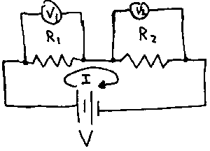
Resistors or other two terminal (having two connections only) devices are said to be in series when the same current must flow through both devices. The conservation of electric charge requires that any charge entering a device must either exit the device at the same rate or build up inside the device. Charge cannot simply disappear or spontaneously appear from nowhere in our circuits. Since our model for resistors makes no provision for building up and storing charge (that's what capacitors will do for us), the current entering a resistor must equal the current leaving. If two resistors are connected one after the other, the same current, I, must flow through both. An example is shown in the figure below. The symbol for a battery, a source of potential difference or voltage appears in this circuit. The positive (higher potential) terminal of the battery is associated with the longer of the pairs of alternating longer--shorter lines.

In this case, the voltage drop across R1 must be
V1 = IR1
and the voltage drop across R2 must be
V2 = IR2.
The sum of the voltage drops should add to the total applied voltage V from the battery:
V = V1 + V2 = IR1 + IR2.
The current is then given by I = V / (R1+R2),
which is the same current that would flow if the two resistors were replaced by a single resistor,
Req=R1+R2.
This argument can be extended to any number of resistors connected in series. The equivalent resistance will be simply the sum of the individual resistances:
Req = R1 + R2 + R3 + ......
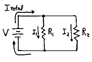
If two or more resistors (or other devices) must have the same voltage drop across them, they are in parallel. In this case a separate current flows through each resistor, but the currents must be distributed so that
V = I1R1 = I2R2.

The total current, I, flowing through such a configuration is just
I = I1 + I2
I = V/R1 + V/R2
I = V(1/R1 + 1/R2).
This same total current would flow if the two resistors were replaced by a single resistor
Req = (1/R1 + 1/R2)-1.
This rule is also easily generalized to an arbitrary number of resistors in parallel:
1 / Req = 1/R1 + 1/R2 + 1/R3 + ......
For parallel resistors, the equivalent resistance is always smaller than any of the individual resistors. Inverse resistances are called conductances, and by placing resistances in parallel, several paths are then available for conduction, increasing the total conductance and decreasing the effective resistance. The smaller resistors in such a network carry more of the current.
Successive application of the series and parallel resistor rules can simplify the circuit below, reducing the circuit to a single equivalent resistance, allowing the total current to be found. Once the total current is known, successive voltage drops can be calculated as well as the currents through individual resistors.

Simplification here.
The series and parallel resistance rules suffice in many situations for analyzing circuits. In some instances, more general techniques are required. These might include situations with multiple voltage sources or even fairly simple arrangements of resistors that don't fit the series or parallel configurations.
To handle these situations, two rules can be applied.
- Kirchhoff's node or junction rule requires that the total current entering a junction (a place where two distinct wires are connected and charges have a choice of direction to go) must equal the total current leaving the junction.
- Kirchhoff's loop rule states that the sum of the voltage drops around any closed path in a DC circuit must be zero.
The node rule is merely a consequence of the conservation of electric charge - charge cannot magically appear or disappear in a circuit. We can consider the loop rule to be a consequence of energy conservation. Imagine following a charge on a trip around a closed path in a circuit. A charge gains some potential energy from the battery or other voltage source in a circuit. In making its way around the circuit, the charge loses this energy, converting it into thermal energy in the resistors. When the charge returns to the battery it has lost precisely the amount of energy it was given and its energy is the same as it was at the start. The changes in energy of the charge at every stage are determined by the voltage differences across each resistor or battery, so if the net change in voltage along a path is zero, so is the net change in energy.
To apply these two rules, the following procedure can be used:
- Examine the circuit to see if the series or parallel rules can be applied to make preliminary simplifications to any parts of the circuit. If possible, re-draw the circuit with the equivalent resistances for those parts.
- Assign a current to each resistor in the circuit, e.g. label the resistors R1, R2, R3,... and assign a corresponding current I1, I2, I3,... to be flowing through each resistor. Be sure to indicate the assumed direction of current flow. Typically these currents are the unknown quantities that you will be solving for.
- Identify the nodes or junctions and write down a node equation for each junction.
- Identify closed paths to use for the loop rule. Often it is easiest to use the smallest closed loops in the circuit. Write down the loop equations for each of these loops.
- Determine how many unknown currents you have. Then find an equal number of independent equations to use to solve for the unknown currents. This is often tricky, since some of the equations you write down may be redundant - i.e. they represent the same mathematical information and are not independent.
- Solve the equations, by brute force, matrix methods, or with software. Once the currents are known, any and all voltage drops may be calculated, too. If you find you get a negative current, it simply indicates that the current flows in the direction opposite to the one that was assumed at the start of the process. No harm is done in making a wrong guess at the outset about which way the current flows through a resistor.
Here is an example of writing down node and loop equations.
A more direct method of applying these techniques is known as Maxwell's method or the mesh-loop method. It eliminates the need for writing down node equations (they are automatically satisfied) and provides the right number of independent equations in a systematic way.
- Assign a current, I1, I2, I3,... to each of the smallest "sub-loops" in the circuit. Think of the current as circulating around the loop, unaware of the rest of the circuit.
- Write down the loop equation for each sub-loop. Be aware that for some resistors, you must take into account two of the loop currents, since you will have two distinct loop currents flowing through the same resistor.
- Solve for the loop currents, again using your favorite technique for solving a few or many simultaneous equations. The equations generated by this method automatically provide enough independent equations.
- Using the loop currents, find the currents through each resistor
and the corresponding voltage drops as needed.
We will make use of the convention of regarding a decrease in
voltage -- commonly called a voltage drop -- as a positive quantity, consistent with the way measuring instruments (voltmeters) report values. As you work your way around a loop (say clockwise), if you follow the same direction as the current through a resistor, the voltage drop to use in the loop equation is positive (+IR). If you find yourself tracing a path that runs opposite to the assumed current direction, the voltage drop will be negative (-IR), since the path you follow takes you from the low potential (voltage) to high potential end of the resistor, and the potential doesn't drop, it increases -- a negative decrease! Similar rules apply when confronting batteries or voltage sources in you path. If the path you follow leads you from the + terminal to the - terminal, the voltage drop for the loop eqution is +V, but if your path runs from the - terminal to the +, then the appropriate voltage drop is -V. Furthermore, with the current loop method, you must realize that some resistors will involve two loop currents and the appropriate voltage drop will depend on either the sum (both loop currents flow through the resistor in the same direction) or difference (the loop currents flow in opposite directions) of the two loop currents. It can be helpful to think back to the gravitational analog for potential. Any time your travels around a path take you "downhill", the voltage drop is positive. If your path takes you uphill, the voltage drop is negative. A ski lift is analogous to a battery: if you ride it to the top, your potential energy (and potential) have increased -- a "negative decrease."
An example of the current loop method is here.
The Voltage Divider
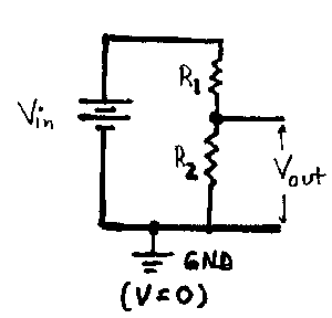
A simple but very important circuit is the voltage divider. In some situations it provides a way to produce small, stable voltages from a fixed voltage source that may be useful elsewhere in a circuit. It is more important in that its behavior and analysis provides the prototype for evaluating many other circuits. It is important to fully understand how to analyze the circuit and to be able to predict its behavior in various limiting cases without resorting to detailed calculations. A typical voltage divider is shown below.

The output of the divider is generally taken as the voltage drop across the lower resistor.
(We have indicated that V=0 at the bottom of the circuit by including the symbol for ground, a common reference point which is assigned a potential of zero volts. Then you can speak of the voltage at any point in the circuit. Any such remark. e.g. "The voltage at point A is 5 volts," is actually a statement about the potential difference between point A and the point in the circuit chosen as ground. The use of the ground point in the circuit as a reference point is always implied in any statement about voltages "at a point" in a circuit. The analysis is straightforward. Proceed in two simple steps: first evaluate the current that flows, and then find the voltage drops that must be present across individual resistors. The current that flows through the circuit follows from treating the resistors in series:
I = Vin / (R1 + R2).
The voltage drop across the lower resistor is just
Vout = IR2 = Vin R2 / (R1 + R2).
The output voltage is always smaller than the input voltage. As the second resistor is decreased, so is the output voltage. If the second resistor is much greater than the first, the output and input voltages are practically the same. If the resistors are equal, the output is one half the input. We shall find the analysis of the voltage divider useful repeatedly, in analyzing AC circuits and filters, biasing transistor circuits, and in setting gains in circuits using operational amplifiers.
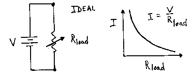
An ideal voltage source is one that will provide a constant voltage, independent of the current requested from it. Such a device does not exist. Every real voltage source is limited in the maximum current it can provide. In a simple circuit with a variable resistance for a load, the current required increases as the load resistance decreases. An ideal voltage source will maintain a constant voltage across the load under all conditions. The current supplied rises indefinitely as the resistance is decreased. Such a source can deliver infinite power to the resistor by suppling a fixed voltage and ever-increasing current as the load resistance decreases, since P=IV.

In practice, the voltage will drop as the current drawn from the voltage source increases. The decrease will be negligible at first, but at some point the voltage across the load will be significantly less than the nominal value of the voltage source. The non-ideal behavior is often modeled by assuming the presence of an additional resistance in the voltage source itself. This resistance is variously called the internal resistance, source resistance, or output impedance. The model of a real voltage source is then simply an ideal voltage source in series with a resistance, Rout. (This quantity is often denoted by Zout. Z is commonly used to denote impedance, a generalization of the idea of resistance that we will see in detail when we discuss AC circuits.)

As a result, any load resistor attached to the source actually forms a voltage divider. The current that will flow through the load is given by
I = V / (Rout + Rload).
This has a maximum value of V/Rout, which occurs when the output wires are short-circuited or "shorted" together by a load resistance of 0.
When the load is an open circuit (infinite load resistance) no current flows and the output voltage is the same as the ideal source voltage. Whenever any current is drawn by the load, the output voltage must be below the ideal value, since there will be a voltage drop of IRout across the internal series resistance, leaving a drop of V - IRout across the output. The smaller the value of Rout, the more nearly ideal the voltage supply. If the load resistance is much larger than the internal resistance of the source, the source appears to be nearly ideal. If, however, the load resistance is comparable to or smaller than the internal resistance, the non-ideal nature of the source must be taken into account.
Current sources provide a constant current through a load, independent of the load resistance. An ideal current source will do so even as the load resistance becomes very large. This will require an ever-increasing voltage to be generated by the current source. In practice this is not the case. Real current sources are limited in the voltages they can generate. This limit is called the compliance voltage. When this limit is reached, the current source acts like a voltage source.

The non-ideal behavior of a current source can be modeled by placing a resistor in parallel with an ideal current source as shown. As
Rload increases, more current will flow through the internal resistor instead of the load. For a current source to be useful, the internal resistance should be large compared to load resistances that will be encountered in use.
Equivalent Circuits
Complicated two-terminal (having two wires to connect a load to) networks built from voltage sources and resistors can be simplified down to two elements in an equivalent circuit. There are two kinds of equivalent circuits to mention here, the Thevenin and Norton equivalent circuits that make use of voltage and current sources respectively.

The Thevenin equivalent circuit consists of a single ideal voltage source in series with a single resistor. The Thevenin equivalent voltage, VTH, is found by calculating the voltage present between the two output connections when the load resistance is infinite -- i.e. the "open-circuit voltage." The Thevenin resistance, RTH, is found from
RTH = VTH / ISHORT
where ISHORT is the current that flows through the load when the load resistance is reduced to 0 - i.e. the output is short-circuited.
The Norton equivalent circuit replaces the network with a single ideal current source in parallel with a single resistor. The Norton current, IN is the short circuit (Rload = 0) output current. The Norton resistance is found from the open circuit voltage, Vopen (infinite Rload):
RN = Vopen / IN = VTH / IN = RTH.
Note that these equivalent circuits are the same as our models for real-world voltage and current sources. While we won't often need to evaluate these equivalent circuits, it's worth remembering that they can serve as a starting point for modeling even more complicated circuits that may contain more sophisticated components, including
transistors and operational amplifiers that we encounter later.
Continue on to the next topic, AC circuits.


