Phys 3041 Notes
©1997 Jonathan Maps. These notes may not be redistributed or duplicated in any form, print or electronic, without permission. Permission is granted to establish electronic hypertext links to these original documents only.
AC Circuit Analysis
AC (alternating current) circuits are those where voltages and currents are time-dependent. They are much richer in possibilities than DC circuits, and we will consider here AC circuits that include resistors. capacitors, and inductors. Our analysis of these circuits will make use of complex numbers to represent the time-dependent currents and voltages. This approach makes analysis of these circuits follow lines very much like those developed for DC circuits.
Resistors in AC Circuits
A simple AC circuit we could construct would be a time-dependent voltage source connected to a single resistor. The voltage source provides a simple sinusoidal voltage: Vo cos(wt).


Vo is called the amplitude of the signal and w is the angular frequency. The period of the signal, T, is the time required for one complete cycle. The frequency, f, is the number of cycles executed in one second (cycles per second), and the unit of measure is the hertz (1 Hz = 1 cycle per second). The frequency is merely the reciprocal of the the period.
The current that flows in the circuit follows from a direct application of Ohm's law and alternates in direction through the resistor. In this circuit, the voltage and current are "in phase", both reach maxima and minima simultaneously.


The magnitude of AC voltages are frequently characterized by two other measures: the peak-to-peak voltage, Vpp = 2 Vo, and the rms (root-mean-squared) voltage.
The rms voltage is the value reported by most multimeters when measuring AC signals, and phrases like "110VAC", which appears next to the power cord on appliances and laboratory instruments, generally mean
110 Vrms. For sinusoidal voltages, Vrms = Vo / 2-1/2 = .707 Vo.
In general the rms value is found by squaring the voltage, computing the average value of V2(t), and then taking the square root.

The rms voltage is useful in computing the average power dissipated in the resistor. The instantaneous power is now given by
P(t)= V(t)I(t),
while the average power is computed over one complete cycle. Since
I(t)=V(t)/R, we have P(t)=V2(t)/R, and finding the average power amounts to calculating the mean squared voltage, shown above. The average power is then just
<P> = <V2> / R = Vrms2 / R.
Capacitors
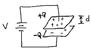
Capacitors are charge storage devices. A convenient model for a capacitor is a pair of parallel metal plates, each with an area A and separated by a distance d. The capacitance of this system is the ratio of the charge stored on the plates (+Q and -Q) to the voltage difference, V, between the plates:
C = Q / V,
or the capacitance can be thought of as the proportionality factor between the voltage and stored charge:
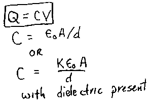
Q = C V.


We will use the latter frequently in our analysis of circuits involving capacitors. The capacitance of the parallel plate system is proportional to the area of the plates (the larger the area, the larger the stored charge at a fixed voltage) and inversely proportional to the separation of the plates. (The electric field is uniform between the plates, so for a fixed charge, a smaller separation implies a smaller voltage: recall that here V = E d.)
In most cases, the capacitance is increased by adding a dielectric material (an easily polarized insulator) between the plates. The capacitance is then enhanced by a factor equal to the dielectric constant of the material.
In a purely DC (time-independent) circuit, capacitors play no role, other than a transitory one when power is first applied. Once charged, nothing more happens to them. Electric charges do not pass through the capacitor. The material between the plates is insulating and adding charge to one plate merely repels an identical charge from the facing plate, leaving it with the opposite charge.
Once the capacitor is charged, it acts like an infinite resistance. Only when the applied voltages and resulting currents vary with time can capacitors play an important role in the performance of a circuit. We will look at the transient response of capacitors later.
Consider a capacitor connected to an AC voltage source.

Since the voltage is time-dependent, the charge on the plates must also change with time:
Q(t) = C V(t).
If charge is added or subtracted to a plate, there must be a current, in this case supplied by the voltage source:
I = dQ/dt = C dV/dt.
This behavior is quite different from resistors. The current is proportional
to the rate of change of voltage. The more rapidly the voltage changes, the larger the current must be in order to satisfy Q = CV. For a simple sinusoidal applied voltage, V(t) = Vo cos(wt), the resulting current is given by:
I(t) = -wCVo sin(wt) = wCVo cos(wt+90).
This exhibits a phase shift between voltage and current of one quarter cycle.

Whenever the applied voltage is at an extremum, the current flowing through the circuit is zero. Conversely, whenever the voltage passes through zero, the current is either a maximum or minimum. In this case, the current is said to lead the voltage: the current reaches a maximum one quarter of a cycle earlier than the voltage does. (An alternate description of the voltage leading the current by 3/4 of a cycle is equally valid, but conventionally the smaller of the two angles is selected in identifying who leads and who lags.)
This phase difference between current and voltage can be treated efficiently with the use of complex numbers. To do this, the real driving voltage (V(t) = Vo cos(wt)) is replaced by an complex driving voltage obtained by adding in an imaginary term:
V(t) = Vo cos(wt) + i Vo sin(wt) = Vo eiwt.
This form has two significant advantages: we will recover something that looks analogous to Ohm's law; and the phase shifts that occur in more complex circuits that include resistors and inductors along with capacitors will fall out very naturally from handling the voltages and currents as complex numbers during calculations. All we need to do is remember to take the real part of our complex results in order to get the real world results.
Applying this to the simple AC voltage source and single capacitor is straightforward.
Q(t) = CVoeiwt
I(t) = dQ/dt = C dV/dt
I(t) = iwCVoeiwt
I(t) = iwC V(t).
Note that in this form the current is now proportional to the applied voltage. This is the analog to Ohm's law for resistors. The analog to resistance is called the impedance of the capacitor:
Zc = V(t) / I(t) = 1 / iwC .
The impedance is an imaginary number. The i contains the information about the 90o phase difference between current and voltage for capacitors. To find the real world current, we merely expand the V(t) into Vo cos(wt) + i Vo sin(wt) and multiply everthing out:
I(t) = iwCVo cos(wt) + i2wCVo sin(wt)
I(t) = -wCVo sin(wt) + iwCVo cos(wt)
and take only the real part of the result:
I(t) = -wCVo sin(wt),
which is just what we obtained before. For a simple circuit such as this using the complex representations for voltage and current may seem excessively elaborate, but the method pays off in being able to treat more complicated circuits by very straightforward techniques.
Note that the impedance of the capacitor is frequency dependent. The impedance is very large at low frequencies, and for a given amplitude Vo for the driving voltage, the
resulting current amplitude Io will be small. The limiting case of this situation is w=0 -- a DC circuit -- where the capacitance has an infinite impedance or effective resistance and no current flows. The other extreme occurs at high frequencies, where the impedance decreases toward zero: a capacitor acts like a "short circuit" at high frequencies, where an alternating current can flow with negligible voltage drop across the capacitor. The magnitude of this impedance is often called the reactance of the capacitor: Xc=1 / wC.
With the idea of resistance generalized to impedance, the rules of series and parallel resistances can be extended to treat general, complex impedances (resistive real impedances of resistors in combination with the reactive imaginary impedances of capacitors, and later inductors) by the same rules. Generalizations of Kirchhoff's rules can then be applied to AC circuits as well. A useful application of these techniques is to RC circuits that can be used to selectively attenuate signals at some frequencies while allowing signals at other frequencies to pass through largely unchanged. Such RC filters are considered next.


